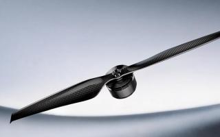
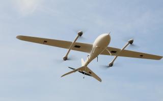
On most agricultural drones, the propeller is selected as part of a matched propulsion system—not as an isolated component. For an aircraft already in service, use the propeller specified or approved for that aircraft or propulsion package. For a new or upgraded spraying or spreading platform, start with payload, battery voltage, rotor layout and airframe constraints, then evaluate an established motor–ESC–propeller combination. OEM, retrofit and custom projects may need a new matching process when standard packages cannot meet the requirements.
This guide follows three practical routes: finding the correct replacement, selecting a matched package for a new platform, and validating a custom configuration. Tank volume or propeller diameter alone cannot establish suitability. Before you start, gather the aircraft or propulsion-system model, rotor layout, deployed clearance, existing components and operating payload.
Start with the Right Route: Replacement, Matched Package or Custom Development
If a propeller is damaged, identify the aircraft or propulsion-system model first. Use the maintenance documentation to confirm the approved propeller part number, direction of rotation and applicable revision. A similar shape, matching diameter or compatible-looking bolt pattern does not establish interchangeability. Include the aircraft model, propulsion model and original propeller markings when requesting a replacement.
For a new platform—or one with a different liquid or granular payload, battery, motor, ESC or rotor count—establish the aircraft requirements before checking which existing propulsion packages can meet them:
- Spraying: Record the aircraft mass, including the battery and spraying equipment, the actual spray-liquid mass, and the mass range from fully loaded to nearly empty.
- Spreading: Record the spreading equipment and material mass, and identify the material being applied. Hopper volume is not a substitute for payload mass.
- Operating schedule: Specify the expected flight duration, refill and battery-change intervals, and operating temperature and altitude ranges.
For most new platforms, this information is used to screen complete propulsion packages, not to select a propeller by diameter or material first. Re-matching the motor, ESC and propeller becomes a separate engineering task only if the available packages cannot satisfy the load, clearance, interface or other defined requirements.
After Choosing a Propulsion Package, Check Diameter, Folding and Transport
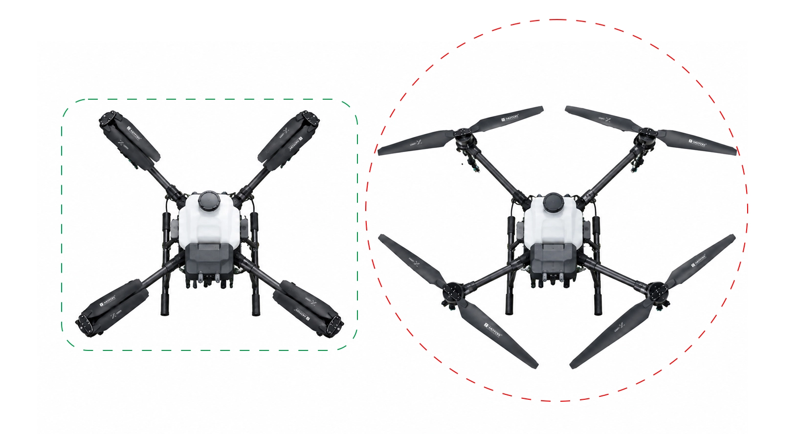
Once you have a matched propulsion candidate, check how it fits the airframe and how the aircraft will be handled in the field: unloading, unfolding the arms, operating and packing it away. Transport dimensions and in-flight clearance are different checks. Folding propellers reduce the space required for storage and transport; they still need clearance for their full diameter when deployed.
Check the spacing between adjacent motor centers, the position of the blades relative to the arms and spraying hardware, and the hub, blade holder and mounting interfaces. No interference in a static drawing is only the first geometry check. Actual clearance must also meet the manufacturer's requirements for structural deflection, assembly tolerances and operation.
For folding propellers, review the specified hardware, installation procedure and inspection requirements. Easier transport does not remove the need to maintain blade holders and connections.
If the aircraft needs to fold for transport, check folding-propeller options within an appropriate matched propulsion package first. The T-MOTOR polymer folding propeller range provides deployed dimensions and mounting information, but the final choice still depends on the specified motor, ESC, rotor layout and manufacturer-approved matching.
What If the Matched Propeller Does Not Fit the Airframe?
First establish whether the constraint is the deployed size or only the transport envelope. If storage is the problem, review the arm and blade-folding arrangement. If there is insufficient clearance in flight, compare other established propulsion packages that can meet the payload requirement within the available space. If none fits, revisit the payload or airframe design, or consider custom propulsion matching.
Alternating inverted motors to create overlapping propeller disks at different heights is not a general-purpose workaround. Partially overlapping adjacent rotors and vertically stacked coaxial rotors are different layouts. Approval for coaxial use does not validate every vertical separation or overlap ratio.
For an overlapping or coaxial arrangement, confirm the propeller’s permitted installation layout and validate thrust, power consumption and vibration for the complete arrangement. Existing single-rotor tests provide an initial reference, not validation of the new layout.
When Does Propeller Material Become a Selection Variable?
When replacing an original propeller or using a proven propulsion package, material preference alone is not a reason to substitute another propeller outside the approved configuration. Material comparison becomes relevant mainly in OEM development, platform modifications or custom matching. Even then, start with models that can meet the required rotational speed, thrust and installation conditions.
In these projects, candidates may include carbon-fiber composite and reinforced-polymer propellers; some reinforced polymers also contain carbon fiber. Compare actual models under the same mission conditions: required thrust, expected contact with spray liquids, permitted cleaning methods, inspection and spare-part availability.
For a genuine custom-matching or redesign project, use the following criteria to compare candidate propellers:
| Operating requirement | What to compare | How to use the information |
|---|
| Required thrust and rotational speed | Model-specific limits and propulsion-combination tests | Eliminate candidates that cannot cover the required operating conditions. Do not infer load capability from the material name. |
| Chemical exposure and cleaning | Compatibility with specific substances and cleaning requirements | Obtain confirmation before selecting a propeller for conditions outside the documented scope. |
| Handling and damage | Inspection methods, damage criteria and replacement instructions | Assess whether the procedures are practical in the field. Material toughness alone does not justify continued use after an impact. |
| Weight and power consumption | Blade or assembly weights measured on the same basis, and power consumption at equal thrust | Do not compare a single blade’s weight with a complete assembly’s weight or infer endurance gains from material labels. |
| Spares and maintenance cost | Pricing, spare-part availability and permitted replacement methods | Include the components that actually need replacing, rather than comparing individual blade prices alone. |
Once two candidates have passed the propulsion and environmental checks, compare total assembly weight on a like-for-like basis, electrical power at the same thrust and actual replacement cost. Those figures are more useful than comparing material labels alone.
What Should You Check for Chemical Exposure, Cleaning and Routine Inspection?
Tell the supplier which spray liquids or cleaning agents the propeller will encounter, their concentrations and the cleaning method. Request compatibility information for the specific product. An agricultural application label does not establish compatibility with every spray mixture, and the protection rating of another propulsion component does not establish the propeller material’s chemical resistance.
Follow the model-specific maintenance instructions. Establish when cracks, deformation, connection problems or an impact require the propeller to be removed from service and replaced. Do not invent a universal replacement interval or return a propeller to service using a repair method the manufacturer has not approved.
For folding propellers, also confirm whether spares are supplied as individual blades, matched pairs or complete assemblies, and which replacement procedures are permitted. The available replacement parts affect field maintenance planning.
How Do You Screen and Validate a Matched System for a New or Modified Platform?
For most new agricultural aircraft, begin with a manufacturer-matched propulsion package rather than selecting the propeller first. As spray liquid or spreading material is consumed, aircraft mass changes. The package must cover the fully loaded condition and the operating points reached as the payload decreases.
Use the aircraft's mass range to determine which thrust levels need checking, then review data for the same motor model and KV, ESC revision, propeller model and corresponding voltage conditions. Do not combine maximum thrust from one setup with the current or efficiency of another.
For an initial estimate, divide aircraft weight by the number of rotors, assuming steady, level hover with equal load sharing. This is only a static baseline. Allowances for maneuvering, attitude changes, environmental conditions and rotor interaction depend on the platform. The final payload must account for those allowances and continuous operating capability.
Start with existing matched options where possible. T-MOTOR's P Series agricultural motor range is one starting point; after identifying a candidate, consult the test data for its specific motor, KV, ESC and propeller combination.
Which Test Data Matter When Reviewing a Matched Package?
Find the test rows closest to the required thrust, then compare input power, current, rotational speed and test conditions. Where possible, compare propellers at equal thrust with comparable supply, installation and environmental conditions. Equal throttle percentages do not necessarily produce equal thrust.
| Data | What they help establish | What else to check |
|---|
| Thrust and input power | Electrical power required to produce the target thrust | Whether the measurements include the same motor and ESC losses. These figures alone do not establish aircraft endurance. |
| Voltage and current | Electrical demand at the operating point | Coverage of the actual supply-voltage range and voltage changes under load |
| Rotational speed | Whether the operating point falls within the propeller’s permitted range | Model-specific speed limits and the test rotor layout |
| Temperature rise and test duration | Thermal behavior under the tested conditions | Measurement location, ambient conditions, cooling and duration |
First check whether the required thrust falls within the recommended operating range, then examine duration and temperature rise. Maximum thrust represents an upper value under specified test conditions. Continuous operation requires sustained-running data at the relevant operating point.
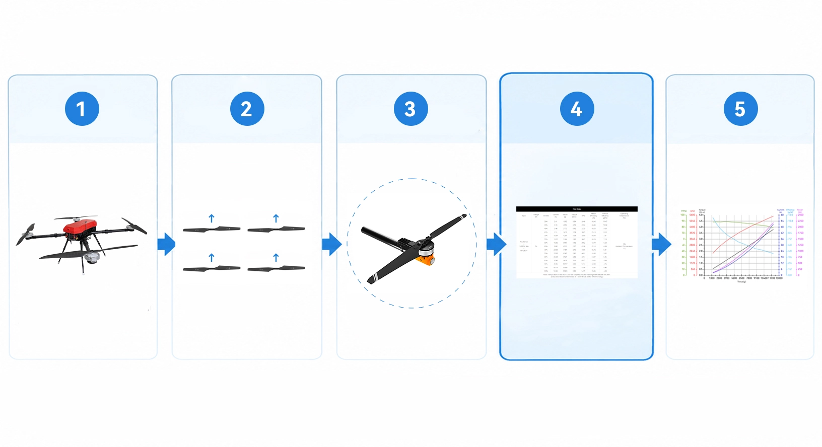
Worked Example: Screening a Matched Package for a 22 kg Quadcopter
This worked example combines hypothetical aircraft requirements with T-MOTOR product specifications and published test data. It demonstrates how to screen an existing manufacturer-matched combination—not how to select the MF3016 independently and then find a motor and ESC for it. It is not a customer flight-test case.
Aircraft assumptions: Loaded takeoff mass is 22 kg, including the airframe, battery, application equipment and material. The aircraft has four non-coaxial rotors, uses a 12S supply and requires folding propellers for transport. Assume the structural design allows a maximum deployed propeller diameter of 800 mm. This is a constraint for this example, not a universal safe spacing between propellers.
Step 1: Check the matched package against geometry, rotor layout and mounting. Consider the MF3016 as part of its manufacturer-matched propulsion setup. T-MOTOR lists its metric diameter as 775.8 mm, below the hypothetical 800 mm limit, so the package remains a candidate after initial dimensional screening. The MF3016 is not recommended for coaxial installations; the non-coaxial layout assumed here is outside that restriction. If the aircraft had room for only a 700 mm propeller, this package would be rejected at this stage, without needing a thrust comparison.
Confirm dimensions against drawings for the version being supplied. The inch and millimeter diameter values on the MF3016 page do not convert consistently, so those entries cannot establish installation suitability. Arm-tube diameter, clamping interfaces and clearance between blades and equipment also require individual checks. Folded dimensions need a separate check.
Step 2: Establish the thrust to look for. Assuming steady, level hover with the load shared equally across four rotors:
22 kg ÷ 4 gives a hover requirement of approximately 5.5 kgf per rotor, or 53.9 N.
This is the fully loaded hover baseline, excluding maneuvering and control allowances.
Step 3: Identify the complete combination and locate adjacent measured points. This example uses P80-X KV100 + ALPHA 80A 12S + MF3016, as identified in the official test table. It is a manufacturer-matched combination, not a proposal to fit the MF3016 to an arbitrary motor.
| Test throttle | Measured voltage | Thrust per rotor | Current | Input power | Rotational speed |
|---|
| 50% | 47.75 V | 4,739 gf (4.739 kgf) | 10.31 A | 492 W | 2,342 rpm |
| 55% | 47.66 V | 5,613 gf (5.613 kgf) | 13.02 A | 621 W | 2,540 rpm |
Source: the KV100 section of T-MOTOR’s official P80-X test table. Both rows use the ALPHA 80A 12S and MF3016. The page specifies an ambient temperature of 25°C. The voltages are the measured values for each row, not rounded to a common 48 V.
The 5.5 kgf requirement lies between these two measured thrust values. The published data therefore cover operating points close to this example’s fully loaded hover baseline. The 55% row is slightly above that baseline and provides a nearby reference point for further validation. Its 13.02 A reading corresponds to 5.613 kgf; it is not a measured current for the aircraft at 5.5 kgf. The test throttle percentages must not be used directly as aircraft hover-throttle settings.
Step 4: Retain the matched candidate and define the remaining tests. The P80-X KV100 + ALPHA 80A 12S + MF3016 combination passes this example's preliminary clearance and rotor-layout checks and has matching bench-test data near the required hover thrust. It can remain on the shortlist, but those results do not establish it as the final configuration.
Next, confirm the supplied revision and installation drawings, then validate operation across the battery’s actual voltage range, maneuvering allowances, thermal behavior over repeated flights and suitability for the agricultural environment. Aircraft testing should also cover operating points at reduced payload and actual spraying or spreading performance. If a requirement is not met, revise the candidate combination or the platform requirements.
The outcome is a manufacturer-matched propulsion candidate with clear validation tasks—not a request for a high-thrust folding propeller independent of the motor and ESC.
What Else Must Be Checked for Repeated Flights?
Compare the test conditions with the planned work cycle: flight duration, refill and battery-change intervals, and propulsion-component temperatures at the start of the next flight.
Request sustained-running records at the relevant operating points. If only short-duration tests are available, include repeated-flight performance in prototype validation. Record load, voltage, current, temperature and rest intervals so that the results can be assessed against the intended mission.
Without duration and thermal-state records, a maximum-thrust test alone cannot establish whether the propulsion system can support repeated operations throughout the day.
How Should Spraying or Spreading Be Validated After a Propeller or Propulsion Change?
A propulsion test bench can measure thrust, rotational speed and power consumption, but it does not establish field application quality.
For a like-for-like replacement, follow the aircraft's prescribed maintenance and return-to-service process. If the propeller model, size or complete propulsion configuration changes, assess the actual application result as well: spray distribution across the swath and deposition at the intended target. Compare those results with power consumption and flight behavior before judging whether the modification meets its goals.
If the propeller model or rotor layout changes, include the following in aircraft validation:
- Spraying: Assess distribution across the swath, target deposition and relevant drift performance against the project requirements. Record nozzle type, flow rate, flight height, speed and environmental conditions.
- Spreading: Assess the actual spread width, distribution uniformity and application rate for the material being used. Record the material, feed settings and flight conditions.
Keep other conditions as consistent as possible when comparing results before and after a propeller change, and record any uncontrolled differences. Lower bench-test power consumption does not establish improved spray deposition or spreading uniformity.
What to Prepare Before Contacting an Agricultural Drone Propulsion Supplier
Providing the following information with the first inquiry helps reduce repeated recommendations based on incomplete requirements.
| Information to provide | Information to request |
|---|
| Aircraft model, or rotor count and layout; original propeller model, if applicable | Specific candidate propeller models, revisions and application limits |
| Maximum permitted propeller diameter, interface drawings, and deployed and transport space | Installation drawings, hub and blade-holder requirements, and rotor-layout restrictions |
| Motor model and KV, ESC model and revision, and voltage range | Test data for the corresponding combination, rather than reference figures from a different setup |
| Aircraft mass, payload range, and spraying or spreading task | Operating points covered by the candidate combination and conditions still requiring validation |
| Temperature, altitude, spray chemicals or spreading material, cleaning method and flight schedule | Operating and maintenance instructions, plus the scope of existing environmental and sustained-running validation |
| Order quantity and spare-part requirements | Pricing, supply arrangements, replacement components and product traceability |
If the propeller supplied with an established propulsion package cannot meet the airframe clearance, interface or operating-point requirements, request a custom matching assessment. Explain the specific constraint: deployed diameter, mounting interface, power consumption at the required thrust or sustained-operation requirements.
For OEM or custom projects, define test conditions and acceptance criteria during the sample stage. Judge feasibility from the proposed configuration and validation results.
Frequently Asked Questions
Do Agricultural Drone Propellers Need to Be Selected Separately?
Usually not for an established agricultural aircraft or a manufacturer-matched propulsion package. Identify the aircraft or propulsion-system model and use its specified or approved propeller. For a new platform, first screen complete propulsion systems against payload, voltage, rotor layout and airframe constraints, then use the propeller matched to the selected package. Separate motor–ESC–propeller matching is mainly relevant to OEM development, retrofits, custom projects or requirements the standard packages cannot meet.
Can I Replace an Agricultural Drone Propeller with Another of the Same Diameter?
Diameter alone does not establish interchangeability. For an established agricultural aircraft or matched propulsion system, use the original or manufacturer-approved replacement first. Verify pitch, mounting interface, rotation direction and applicable revision. A different propeller model is a propulsion-configuration change, not a routine replacement.
What Propeller Size Is Needed for a 20 L, 30 L or Larger Tank?
Tank capacity cannot determine a universal propeller diameter. Use actual liquid mass, loaded aircraft mass including the battery and application equipment, rotor count, battery platform and available airframe space to identify an appropriate propulsion package. Then use the propeller specified for that package. Two aircraft with identical tank capacity may use different propulsion systems and propeller sizes.
Can I Replace Just One Damaged Blade on a Folding Propeller?
Follow the model-specific maintenance instructions and permitted replacement options. Availability of individual spare blades does not mean they can be combined with any existing blade. Confirm revision, pairing and assembly requirements. If the manufacturer has not specified a permitted replacement procedure, obtain confirmation first.
Are Low-Noise Propellers Suitable for Agricultural Drones, and How Should They Be Evaluated?
Noise can be a selection criterion, but the propeller must still meet the load, clearance and propulsion requirements. Check whether acoustic measurements were taken at the same required thrust and whether measurement distance, direction, frequency weighting, environment and rotational speed are comparable. Material, appearance or a low-noise label alone cannot establish the actual noise reduction.
Should Flight Controller Settings Be Checked After Changing Propellers?
Distinguish an identical replacement from a configuration change. When replacing a propeller with the same model and specification, follow the aircraft’s maintenance and return-to-service procedure. If the propeller model, size or propulsion combination changes, review the relevant settings and flight behavior under the platform’s commissioning procedure before deciding whether retuning is needed. Do not copy settings directly from another aircraft.
If you know your payload, rotor layout and transport constraints but are unsure which agricultural propulsion package to use—or the standard packages do not meet your clearance, interface or operating requirements—send your aircraft specifications, available space and existing propulsion details to T-MOTOR to discuss a matched option or a custom configuration for further validation.