Selecting an ESC for an agricultural drone is not simply a matter of choosing a current rating. The ESC has to match the actual motor-propeller load at the intended operating condition, together with the battery voltage, operating current, control protocol, cooling arrangement and working environment.
Most projects start from one of two situations:
If the motor and propeller are already defined, select and verify a standalone ESC from validated motor-propeller data.
If the motor, ESC and propeller are all still open, start by evaluating a matched propulsion system before selecting the components separately.
A practical selection sequence is:
Battery voltage → required thrust → motor-propeller operating current range → ESC current capability → control protocol → cooling and protection → final compatibility check
Start with the Loaded Motor-Propeller Demand
A spraying drone takes off with more than liquid payload. The battery, frame, pump, plumbing and other equipment all contribute to the aircraft mass, so calculations should start from the loaded takeoff weight, not tank capacity alone.
For a conventional multirotor with vertical thrust axes and approximately equal rotor loading:
Hover thrust per rotor (N) ≈ takeoff mass (kg) × 9.81 ÷ number of rotors
If the manufacturer’s test data are given in kgf or gf:
Hover thrust per rotor (kgf) ≈ takeoff mass (kg) ÷ number of rotors
1 kgf ≈ 9.81 N = 1,000 gf
This value represents level hover only. Climb, attitude correction, wind and unequal rotor loading all require more thrust, so the hover point should not be treated as the highest design point of the propulsion system.
Once the thrust requirement per rotor is known, locate that thrust in the test data for the intended motor + propeller + battery voltage combination and read the corresponding current. That operating point is more useful for ESC selection than motor size, KV or tank capacity.
When reading the test data, pay attention to at least two parts of the operating range:
- current around the normal loaded operating point;
- current reached in the validated higher-thrust range.
Also confirm what the reported current represents. ESC battery-input current and motor phase current are not the same quantity. A current measurement taken at the aircraft’s main battery may also include the spray pump and other onboard equipment.
For a broader explanation of complete propulsion matching, see the Multirotor UAV Propulsion System Matching Guide.
How Much ESC Current Is Enough?
There is no reliable agricultural-drone rule such as “hover current × 1.5.” The ESC has to cover the electrical load across the part of the operating range the aircraft will actually use, rather than only the hover point.
Check the Battery’s Maximum Voltage First
Use the battery voltage at full charge when checking the ESC.
For conventional LiPo cells charged to 4.2 V per cell:
- 12S fully charged: 50.4 V
- 14S fully charged: 58.8 V
The ESC’s published input-voltage range must cover that value. A higher current rating cannot compensate for an ESC whose voltage limit is too low.
Changing battery voltage also changes the operating condition of the motor-propeller combination. A combination validated at one voltage should not automatically be carried over to a higher voltage without matching data.
Separate Sustained Load from Short-Duration High Load
For a standalone ESC with a published continuous-current rating, the current during normal loaded operation should remain within that rating under the intended cooling conditions.
Short-duration loads during climb or attitude correction should then be checked against the published peak-current value and its permitted duration.
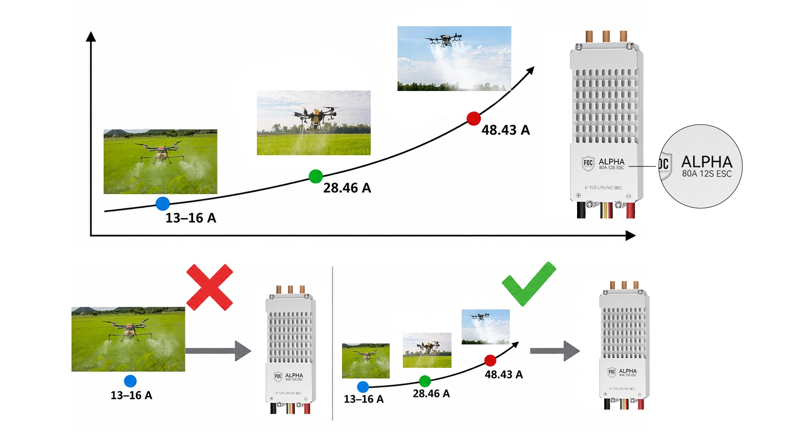
A common mistake is to divide the ESC rating by hover current and call the result a safety margin. For example, a propulsion system may draw only about 14 A around hover but approach 50 A in the higher-load region of its test data. In that case, describing a 60 A ESC as having “four times the margin” has little practical meaning.
At the same time, simply choosing a larger ESC does not solve a voltage mismatch, unsupported control protocol, incorrect motor configuration or inadequate cooling.
Evaluate Cooling and Protection in the Installed Aircraft
Validate the ESC in Its Installed Position
The same ESC can operate under very different thermal conditions on an open test stand and inside an aircraft arm or enclosure.
Validation should reflect the actual installation, including:
- mounting position;
- airflow;
- wiring arrangement;
- enclosure or protective cover;
- loaded flight condition;
- ambient temperature;
- sortie duration.
An empty-tank hover does not represent a fully loaded agricultural mission. Repeated sorties also matter because the next flight may begin while the propulsion system is still warm.
If ESC temperature telemetry is unavailable, verify the thermal condition through installed testing rather than using motor temperature as a substitute for ESC temperature.
Spray Protection Is More Than an IP Number
Agricultural UAVs are regularly exposed to spray droplets, mud and repeated cleaning. Product-level protection matters, but cable exits, connectors and mounting interfaces can still become weak points. Any protective cover also has to preserve the airflow needed for cooling.
IP codes should be read carefully. The first position indicates protection against solid objects and dust, while the second indicates protection against water. An X means that no rating is stated for that position. For example, IPX6 states the water-ingress rating but does not state a dust-protection rating.
Do not transfer an IP rating from another ESC in the same series unless the manufacturer publishes that rating for the exact product.
Choose the Control Architecture Before the ESC Model
The flight controller and ESC must use a compatible control method.
In T-MOTOR’s current industrial ESC range, the ALPHA Series is primarily PWM-oriented, while the V Series provides DroneCAN/PWM options.
PWM can be sufficient when the aircraft only requires basic throttle control. If the project requires supported ESC-side telemetry and CAN communication, choose a product that explicitly provides the required interface.
For a series-level comparison, see the T-MOTOR PWM vs DroneCAN Selection Guide.
A connector that physically fits does not prove protocol compatibility. Before purchasing, confirm the supported signal, wiring and configuration procedure for the exact ESC and flight controller.
Route 1: The Motor and Propeller Are Already Defined
When the motor and propeller have already been selected, filter standalone ESCs by voltage, current capability and control method before comparing secondary factors such as size and weight.
T-MOTOR Standalone ESC Examples
| ESC | Input voltage | Continuous current | Peak current | Control | Selection note |
|---|
| ALPHA 60A 12S V1.2 | 18–50.4 V | 60 A | 80 A / 10 s | PWM | For standalone 12S configurations where the motor-propeller combination and ESC program have been confirmed |
| ALPHA 80A 12S | 18–52.2 V | 80 A | 100 A / 10 s | PWM | For 12S configurations requiring more current capability than the 60 A model |
| V80A 14S | 18–60 V | 40 A | 80 A /<10 s | PWM/CAN | Can cover 14S; suitable for evaluation where CAN is required, but continuous current must still be checked against 40 A |
The model name alone does not represent the current that can be used continuously. For example, the V80A 14S has a published continuous-current rating of 40 A, while 80 A is its short-duration peak value.
The published input-voltage ranges of the two ALPHA examples above fall within the 12S range. A conventional 14S LiPo can reach 58.8 V when fully charged, which is above the published limits of both products.
Any standalone ESC decision still has to return to the exact motor, propeller, battery and ESC configuration. If the manufacturer does not publish matching information for that combination, confirm it before flight.
Route 2: The Propulsion System Is Still Open
If the motor, ESC and propeller have not yet been defined, starting with a matched propulsion package is generally more straightforward than selecting the three components independently and then validating compatibility.
T-MOTOR provides propulsion solutions for agricultural UAV applications. The A Series Modular Propulsion System is a useful example of how a complete propulsion package can be evaluated.
A Series Agricultural UAV Propulsion Comparison
| System | Recommended battery | Rated thrust per arm | Quadcopter takeoff weight | Hexacopter takeoff weight | Propeller |
|---|
| A6-X | 12–14S LiPo | 3.5–5 kg | 14–20 kg | 21–30 kg | MF2311P |
| A6L-X | 12–14S LiPo | 4–5.5 kg | 16–22 kg | 24–33 kg | MF2407P |
| A8-X | 12–14S LiPo | 5–7 kg | 22–30 kg | 30–42 kg | MF3119P |
These specifications belong to complete propulsion systems. They should not be taken as evidence that a standalone ALPHA ESC can directly replace the original ESC in an A Series system.
For example, the published A6L-X configuration includes:
- A6L-X KV160 motor
- 14S FOC 80A ESC
- MF2407P propeller
- 12–14S recommended battery
- IPX6 complete-system rating
The same A6L-X page also lists a 61 V maximum ESC voltage, PWM/CAN control, and DroneCAN / UAVCAN / CUBE CAN protocols.
The “80A” in 14S FOC 80A ESC should not be interpreted as an 80 A continuous-current rating. In the A6L-X specification, 80 A is the short-duration peak current in an open environment at ≤60°C.
Worked Example: Finding the A6L-X Operating Point for a 22 kg Quadcopter
Assume a conventional 22 kg quadcopter and evaluate the A6L-X as the candidate propulsion system.
Step 1: Calculate Hover Thrust per Rotor
22 kg ÷ 4 = 5.5 kgf per rotor
A 22 kg quadcopter sits at the upper end of T-MOTOR’s published 16–22 kg quadcopter takeoff-weight range for A6L-X.
Step 2: Find 5.5 kgf in the Published Test Data
T-MOTOR publishes bench-test data for the following combination:
A6L-X KV160 + 14S FOC 80A ESC + MF2407P at 54 V
| Test throttle | Thrust per unit | Current |
|---|
| 55% | 4.469 kgf | 10.34 A |
| 60% | 5.294 kgf | 13.21 A |
| 65% | 6.056 kgf | 16.10 A |
| 80% | 8.799 kgf | 28.46 A |
| 100% | 12.148 kgf | 48.43 A |
Note: The figures above are T-MOTOR bench-test data for the stated A6L-X configuration and are intended as selection reference data for that configuration. Installed-aircraft performance still needs to be verified under the actual mission conditions.
The 5.5 kgf requirement falls between the 60% and 65% test points. For this test configuration, the hover-region current is therefore roughly 13.21–16.10 A.
That value describes the operating point around hover. It is not the ESC current-rating target. In the same test table, current reaches 28.46 A at 80% throttle and 48.43 A at 100% throttle. Selecting an ESC from the 13–16 A hover region alone would significantly understate the current the propulsion system can reach.
Step 3: Check the Battery and Control Limits
A conventional 14S LiPo reaches 58.8 V when fully charged. The matched ESC listed for A6L-X has a published maximum voltage of 61 V, so the published system covers that battery platform.
The two 12S ALPHA examples above have published voltage limits below 58.8 V, so they should not be carried directly into this 14S example.
A6L-X also supports PWM/CAN and lists DroneCAN, UAVCAN and CUBE CAN protocols. Its integration path is therefore different from the PWM-only ALPHA examples.
Step 4: Read “80A ESC” Correctly
The A6L-X page identifies the matched controller as a 14S FOC 80A ESC, but the 80 A value in the specification is a short-duration peak current rather than a continuous-current rating.
For that reason, 80 A ÷ 13–16 A is not a valid way to calculate a continuous-current safety margin.
The practical conclusion is that A6L-X is a matched propulsion package with published thrust/current test data, battery limits and communication specifications. The installed aircraft still needs to be validated under its actual mission, cooling and environmental conditions.
Turn the Selection into a Purchasing Specification
Whether you are purchasing a standalone ESC or confirming a complete propulsion system, provide enough information for the supplier to verify the configuration.
| Information to provide | Confirmation to request |
|---|
| Battery chemistry, cell count and maximum charged voltage | Approved ESC input-voltage range |
| Motor model and KV | Matching ESC configuration |
| Propeller model and size | Validated motor-propeller combination |
| Loaded takeoff weight and rotor layout | Required thrust per arm |
| Normal and higher-load operating current | Applicable continuous and peak-current limits |
| Flight controller | PWM/CAN compatibility and setup |
| Telemetry requirement | Supported feedback data and communication method |
| Mounting position and airflow | Cooling requirements |
| Spray and cleaning exposure | Protection and maintenance requirements |
| Cable and connector requirements | Correct production configuration |
For replacement projects, also record the exact ESC model, hardware revision, program or firmware, and wiring configuration already installed.
For a complete propulsion system, record the motor, ESC and propeller as one configuration so that later component replacement does not unintentionally break the validated match.
Frequently Asked Questions
What Amp ESC Do I Need for an Agricultural Drone?
Start with the published current data for the intended motor, propeller and battery combination. Normal loaded operating current should remain within the ESC’s continuous-current capability where that value is published. Higher-load conditions should then be checked against the peak-current value and its permitted duration.
Voltage and control compatibility still need to be checked separately.
Can I Choose an ESC from Hover Current Alone?
No. Hover is only one operating point. In the A6L-X example above, a 22 kg quadcopter operates around 13–16 A near hover, while the same published test reaches 48.43 A at 100% throttle.
Why Is A6L-X Called an “80A ESC” If Hover Current Is Only About 13–16 A?
Because hover current does not represent the complete load range. More importantly, the 80 A figure on the A6L-X page is a short-duration peak-current value, not a published 80 A continuous-current rating.
For that reason, dividing 80 A by hover current does not give a valid continuous-current safety margin.
Can a 12S ESC Be Used with a 14S Battery?
Only if the manufacturer’s published maximum input voltage covers the battery voltage at full charge.
A conventional 14S LiPo reaches 58.8 V. The published voltage limits of the ALPHA 60A 12S V1.2 and ALPHA 80A 12S are below that value, while the V80A 14S is published for 18–60 V.
Does an Agricultural Drone Need DroneCAN?
Not necessarily. PWM can be sufficient when the system only requires basic throttle control.
If the project requires a CAN interface and ESC-side communication, select a product or complete propulsion system that explicitly supports those functions. The T-MOTOR V80A 14S and A6L-X both have published PWM/CAN support.
Should I Buy a Standalone ESC or a Complete Propulsion System?
If the motor and propeller are already fixed and reliable matching and load data are available, the standalone ESC route is appropriate.
If the motor, ESC and propeller are all still open, starting from a manufacturer-defined complete propulsion system generally makes compatibility easier to control.
Final Selection Check
Before approving an agricultural UAV ESC, confirm these six points:
- The ESC input-voltage range covers the battery’s maximum charged voltage.
- The motor-propeller combination has usable load data or manufacturer matching information.
- Normal and higher-load current remain within the ESC limits published for the selected product.
- The ESC supports the control interface required by the project.
- The installed aircraft provides adequate cooling and environmental protection.
- Component versions and configuration details are recorded accurately for purchasing and future replacement.
If the voltage, compatibility, communication method or installation conditions do not match, simply choosing a higher-current ESC will not solve the problem.
Need help reviewing a standalone ESC or a complete agricultural UAV propulsion system? Send T-MOTOR the battery specification, motor and propeller details, rotor layout, loaded takeoff weight, flight controller and communication requirements.
Discuss your agricultural drone propulsion requirements